Good day to the blog viewer. My name is Nazirul Izzuan Bin Zul Akmar (D20111050109). Today I'll be doing a simple tutorial about making a Gundam using Autodesk 3ds Max software for making 3D models. Firstly of course you need the software first and install it to your computer. Next is u find what ever blueprint that your want to used but in this case,we'll be doing a Gundam so just download the blueprint from the link below so that it is easier for you.
After downloaded it, open 3ds Max and then set up project folder first and then press Make New Folder and rename it to your project name.
HEAD
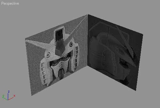
After that is done, arrange the blueprint so that it will look like the image below.
Next step is switch to Front viewport, create a plane with 2 x 6 segments. Position this plane in front of Gundam face. Right click and choose Convert To> Convert To Editable Poly. Apply material to this plane. I use simple green color and decrease its Opacity value to 50%. So I can see blueprint behind. Turn on Smooth and Highlight (F3) or Edge Faces view (F4) in Front, Left and Perspective viewport.
In Modify tab, activate Polygon selection. Select half of polygons, and delete. De-activate all sub-object selections and apply Symmetry modifier. Use X axis with Flip option active. From now on, you only need to create half of the head. By doing this, we don't have to adjust it one by one. The other half will be mirrored by Symmetry modifier.
In Modifier Stack, click plus (+) sign left of Editable Poly and highlight Vertex selection. In Front and Left viewport, move each vertex to match the background. Use image below for guideline.
Change to Edge selection. Select several edges like image below. There are 6 edges you need to select. You can select more than one edge by holding Ctrl while selecting. Then click Connect in Edit Edges rollout to create connecting edges.
In Front viewport, select all upper edges. Move them up while holding Shift (Shift+drag) to create more edges. Next, in Left viewport, move cloned edges to the left, creating eye shape.
In Front viewport, Shift+drag upper edges up twice. Change to Vertex selection, and move vertices to create eye shape. Finished result is shown in the most right image below.
In Left viewport, select 2 edges like image below. Shift+drag once to create more edges.
Fill the triangle gap. Change selection to Polygon. Activate 3D snap toggle to make you precisely selecting vertex position. In Edit Geometry rollout click Create button. In Perspective viewport, click in order to create polygon (For example 1-2-3-1). Turn off 3D snap toggle when finished.
Shift+drag edges like images below.
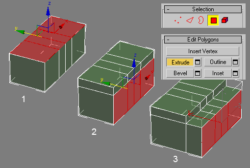
Select three polygons. In Edit Polygons rollout, click Extrude button. Click and drag in selected polygons to create extrusion. Watch Left viewport to see how much extrusion needed.
Using Select And Uniform Scale resize extruded polygons to make them smaller. Then, in Front viewport move polygons to the right.
Don't deselect all selected polygons. Use Inset, and then Bevel inward.
Change to Edge selection. Select all vertical edges like image below. Then apply Connect to divide these edges. Finally, move vertices to match blueprint behind. You can look at final result at right image below.
Now, you will create basic head shape of Gundam. I will use simple technique by using an extended primitive available in 3dsmax. It saves times a lot when you use primitive to create more complex object like this Gundam head.
Creating Basic Head Shape
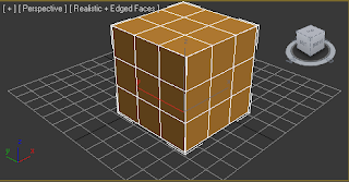
Go to Create>Geometry tab. Choose Extended Primitives from drop down list. Then click ChamferCyl button. Click and drag in Top viewport to create Chamfer Cylinder. Go to Modify tab and change some parameters. Use parameters at image below. When finished, position Chamfer Cylinder in the middle of Gundam head blueprint.
Right click Chamfer Cylinder and choose Convert To>Convert To Editable Poly. In Left and Top viewport, select polygons like image below and delete them.
Change selection to Vertex. Select all vertices. Using Select and Non-uniform Scale Tool, resize along X axis. Position Chamfer Cylinder again until it looks like left image below. Apply Chamfer Cylinder using the same transparent material. Next, in Left viewport move vertices in Chamfer cylinder the same level as vertices in face object.
Rotate view in Perspective viewport until you can see upper part of Chamfer Cylinder. Open Grid and Snap Settings dialog box (from top menu Customize>Grid And Snap Settings). Activate Midpoint. This will allow you to select middle of edge precisely. Close dialog box when finished. Activate Edge selection. Turn on 3D snap toggle. In Edit Geometry rollout, click Cut button. Cut edges from top to bottom (look at image below). Note: Right click to finish cutting.
In Left viewport, cut like left image below. Change to Polygon selection. Select several polygons in the bottom part of Chamfer Cylinder (right image below). Delete them. When finished, go to Edit Geometry rollout. Click Attach button. Next, click face object to make both object combined.
Last step, zoom in gap area between previous two objects. Activate Vertex selection. In Edit Vertices, click Target Weld. This feature is used to weld one vertex to another. Before you begin, activate 3D snap toggle. To weld, just click one vertex (A), and then click another target vertex (B). Final result is shown in small image in bottom right.
In previous tutorial you had basic Gundam head shape. It's still far from finish.Right now, your Gundam head is like a cylinder than a robot head. So, let's adjust the head to create more rounded and refined shape. You will also add several small holes in both left and right side.
Adjusting Head Shape
Activate Edge selection. In Left viewport cut several times like image below. Then, move vertices to match blueprint behind.
Change selection to Polygon. Select several polygons in Left viewport. Next, in Front viewport, move polygons along X axis a little bit.
Back again in Left viewport, select polygons like image below. In Edit Polygons rolllout, click Extrude button. Click and drag in viewport to add extrusion. Watch blueprint in Front viewport to control how much extrusion needed.
Activate Vertex selection. You need to move some vertices (as a result from extrusion). Before that, in Top viewport select one of vertex (for example vertex inside red circle) and look at its X coordinate in bottom part of the screen. Then, select vertices you want to move and enter new X coordinate. Note: Don't use the same X coordinate from image below. You should check yourself.
Still in Vertex selection. Select several vertices like shown in image below. Move them down a little bit.
Right now, our Gundam head is like a cylinder. Next, you will modify it. In Left viewport select several vertices like image below. Open Soft selection rollout. Activate Soft selection with Falloff=49 and Bubble=1.15. Move selected vertices to the left and you'll get rounded head shape. Turn off Soft Selection for a while and move several vertices position manually (vertices inside white circle) to make smooth head shape.
Select four vertices in Left viewport. Then, activate Soft Selection again with the same values like before. In Front viewport, move selected vertices outward the head. When finished, turn off Soft Selection.
Next, we will modify area at the side of the head. I don't know what this area functions. Maybe for air circulation. In Perspective viewport, select two polygons like image below. In Edit Polygons rollout, click Settings button right next to Inset. Enter Inset Amount=2.5 and click OK. Next, click Settings button right next to Bevel. Enter Height=-6.5 and Outline Amount=-1. Click OK. Next step, apply the same procedure to other polygons (marked by by white arrows)
Activate Polygon selection. Delete half of polygons. Turn off all sub-object selection. Apply Symmetry modifier. As usual, use X axis and Flip active. Bottom image shows your Gundam head so far.
Finished Gundam head up to this point.
After your Gundam head shape is much better in previous tutorial, now, you will modify forehead area. You will create a shape like a hat in forehead area.
Modify Forehead Area
Activate Polygon selection. Rotate view in Perspective viewport until you can see inner side. Select polygons in the rear part of the head (look at left image below). Press "Delete" in keyboard to remove them. Change selection to Edge. Select all edges from forehead to rear of the head (look at right image below).
In Top viewport, Shift+drag to the right. You should position these selected edges in the same exact X coordinate with existing edges (red circle). Note: Don't use X values shown here. You should check yourself.
After that, go to Left viewport. Activate Vertex selection. Select vertices in forehead area. Move to the right. Move each vertex to match blueprint behind.
By the way, you can always increase or decrease material transparency to help you clearly see the model. Rotate view in Perspective viewport until you can see top of the head. Select 2 edges like shown in image below. In Edit Edges rollout, click Settings button right next to Connect. In opened dialog box, enter Segments=2 and Slide=2. Click OK.
From top menu click Customize>Grid And Snap Settings. In dialog box, check Edge/Segment. Now, you can precisely select anywhere along an edge. Cut edges in 2 areas like image below.
Change selection to Vertex. Move vertices to create smooth surface. Look at image below for reference.
Final step in this section. Change to Polygon selection. In Edit Geometry rollout click Create button. Fill the gap between forehead and eye area by creating new polygons. Use Create several times until all gap is filled.
Next, you will add important element in every type of Gundam head. You will create roman helmet like shape and V-shape emblem.
Adding Details on Top of The Head
Convert object into Editable Poly. Activate Polygon selection. Select polygons like image below. Bevel the polygons.
Change selection to Vertex. In Left viewport, move vertices to match blueprint behind.
Activate Edge selection. Select edges in beveled polygons (left and right).In Edit Edges rollout click Chamfer button. Click and drag in selected edges to chamfer a bit. Next, change selection to Polygon. Select one polygon like image below.
Apply Inset and Bevel inside. Repeat the same procedure with the back of the head.
Next, cerating V-shape emblem. In Left viewport, move vertices to match blueprint. Then, Cut like right image below.
In Front viewport, using Select and Non-Uniform Scale tool modify vertex position along X axis.
Select diamond shaped polygons. Apply Bevel. Move several vertices in Left viewport to match blueprint.
Activate Edge selection. Cut like left image below. Also cut the other side. Change to Polygon selection. Select triangle shaped polygons (both side).
In Edit Polygons rollout, click Settings button right next Extrude. Enter Extrusion height like image below. Next, move extruded polygons up. Resize using Select and Uniform Tool, make it much smaller. In Left viewport, move selected polygons to the back.
I am sure you are satisfied with your Gundam head model now. But,your Gundam head can be a lot better by adding some details. This tutorial and last one explain how to add details. Ok, let's begin by adding some detail in the face.
Detailing The Face
Select all polygons creating the eyes. In Edit Polygons rollout click Settings button right next to Bevel. In opened dialog box Enter Height=1,5 and Outline Ammount=-1.8. Gundam model should now has better eyes, comparing to the flat ones before.
Next, we will add details in mouth area. Change to Edge selection. Select 3 vertical edges like image below. In Edit Edges rollout, click Settings button right next Connect. In opened dialog box enter Segments=4 and Pinch=-23. Next, using Cut create another additional edges like image below. Cut in both sides. Be sure you activate 3D snap toggle before.
Change to Vertex selection. Modify vertices position like image below. Next, change to Polygon selection. Select 4 polygons like right image below. Apply Extrude with negative value (inside extrusion).
Next, we are going to add details in chin area. Activate Edge selection. In Perspective viewport, rotate view until you can see bottom part of the head. Select edges in chin area (look at image below). There are 8 edges you need to select. In Left viewport, shift+drag selected edges. A little bit down and left.
Still in Edge selection. In Front viewport cut like image below. Activate 3D snap toggle before cutting.
Select polygons like image below. Use Extrude twice. The first one is light extrusion. The second is longer. Next, using Select And Uniform Scale make extruded polygons smaller. Finaly, move vertices to match blueprint behind.
Just one detail again. You will add head lamp in both head sides.
One More Detail and It's Done!
53. Enter Polygon selection. Select half of object. Delete them. Turn off any sub-object selection. Next, create cylinder in Front viewport. Use values below. Position cylinder using blueprint as reference (look at image below).
Make sure Gundam head object is selected. In Command Panel, go to Create>Geometry tab. Choose Compound Objects in drop down list. Click Boolean button. In Pick Boolean rollout, click Pick Operan B button. Then click cylinder in viewport. By default Boolean operation is substraction, therefore there's a hole in Gundam head. Just in case the hole created in wrong place, click plus (+) sign left of Boolean in Modifier Stack. Highlight Operands. In Parameters rollout select Cylinder01. Then you can adjust hole position.
After that, convert Gundam head object into Editable Poly. Activate Border selection. Select border in head lamp hole. Shift+drag inside. Then, in Edit Geometry rollout, click Y button right next to Make Planar. You will get nice head lamp hole. When finished, turn off all sub-object selection.
Leave Gundam head for a moment. We will create head lamp from separate object. Create cylinder using previous values (Radius=9, Height Segs=1, Sides=12), but with lower Height=30. Follow steps at image below. (1) Convert into Editable Poly. Select cap polygon. (2) Resize and make it smaller. (3). Use Inset. (4) Use Bevel inward. (5). Apply Bevel again twice. This time outward, making round shape. (6). Finished head lamp.
Position head lamp object into its position.
After that, make sure Gundam head object is selected. In Edit Geometry rollout, click Attach button. Then click head lamp object in viewport. Now, you have finished half of Gundam head. Finally, apply Symmetry modifier. Use X axis with Flip active. Congraturaltions! Gundam head modeling tutorial is finished. Image below shows rendered result.
Your finished Gundam RX-78-2 head.
I altered my Gundam head to make it a bit different from the tutorial. This is the result.
BODY
Creating Basic Body Shape
First, let's create basic body shape. To follow this tutorial, you need to this file, Gundam blueprint. When you open 3dsmax file (gundam_fulbody_start.max), you will get scene like image below.
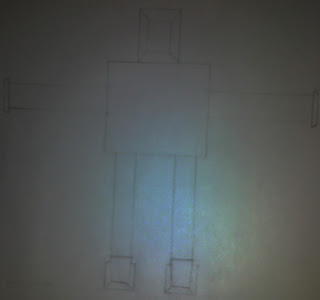
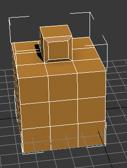
In Front viewport, create box with 4x1 segments like image below. Right click and choose Convert To> Convert To Editable Poly. Apply material to this box. I use simple green color and decrease its Opacity value to 50%. So I can see blueprint behind. Turn on Smooth and Highlight (F3) or Edge Faces view (F4) in Front, Left and Perspective viewport.
In Modify tab, activate Vertex selection. In Front viewport select vertices in four areas using region / window selection like image below. Using Select And Uniform Scale tool, move vertices closer to the center by clicking and dragging along X axis. Look at blueprint behind for reference.
Change selection to Polygon. Select polygons on top and front faces, and extrude them. Note: To select more than one polygon, hold Ctrl while selecting .
Change to Vertex selection. Move vertices like image below. Match blueprint behind.
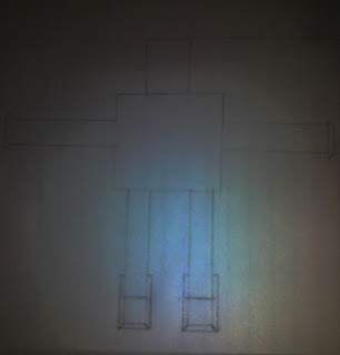
Change to Polygon again. Select all polygons in the bottom area of box. Apply Bevel four times. Notice that the first and third bevel is applied with slight amount.
Activate Vertex selection. Modify vertices position based on blueprint behind.
The first part of Gundam body modeling tutorial is finished. Image below shows Gundam basic body shape. Next step is modify this basic body shape.
After you have created Gundam basic body shape in previous tutorial, you will modify tthe basic body shape and create more detailed shape. In this tutorial, you will modify stomach and neck area. The same techniques applied here, for example Extrude.
Creating Details in Stomach and Neck
Select polygons in stomach area (look at image below). Apply Extrude.
Change selection to Vertex. Move vertices like image below.
Back to Polygon selection. (1). Select polygons in stomach area. (2). In Front viewport use Select And Uniform Scale along X axis to scale polygons width. (3) In Edit Polygons rollout, click Inset button. Click and drag in selected polygons to apply Inset a little bit. (4). Then apply Extrude.
Change to Edge selection. Select horizontal edges like left image below. In Left viewport, move selected edges to the left (inside). Right image below shows the result.
Next, we are going to adjust the neck area. Select polygons in the chest area, and apply Inset. Use Select And Uniform Scale Tool in X and Y axis to adjust polygons shape (right image).
Activate Vertex selection. In Front viewport, select several vertices in neck area. Using Select and Uniform Scale Tool along X axis, widen vertices position.
Change to Polygon selection. Select polygons like most left image below. Apply Inset (middle image) and select surrounding polygons resulted from Inset (right image).
Apply Extrude to the selected polygons. Then, in Left viewport adjust vertices position based on blueprint behind.
Modify vertices position like shown in image below.
In Left viewport, select vertices like left image below. Then, using Select and Uniform Scale tool along X axis move vertices closer to the center.
After you have created basic body shape and modify a little bit in previous tutorial, now you will adjust the bottom part of Gundam body.
Creating Lower Body Details
Select a few polygons in bottom part of body object. First, apply slight Extrude. In Front viewport use Select And Uniform Scale Tool along X axis to make polygons width smaller (middle image below). Then apply Extrude three times.
Select polygons in front and back of previous extruded faces. Apply Extrude in both sides (front and back).
Activate Vertex selection. Adjust vertices position in Left viewport.
Select polygons like image below. Apply Inset and Extrude with negative value (inward).
Next, we are going to add details in chest. First, select half of polygons in body object. Delete them. Change selection to Edge. Select edges like middle image below (5 edges). In Left viewport, move those edges to the right
After creating lower body details, let's continue creating details in chest area.
Adding Details To The Chest
Select one edge in chest area (look at image below). Then in Front viewport, move this edge a little bit closer to the center and up.
Next, (1). Select one polygon in chest. (2). Apply Bevel and move the selected polygon closer to the center along X axis. (3). Apply Inset. (4) Finally, give negative extrusion value (inward). When finished, don't deselect anything.
While you have one polygon selected, go to Edit Geometry rollout. Click Detach button. In opened dialog box, choose Detach To Element and click OK. This polygon will be detached as an element. Don't deselect this polygon. Click Hide Unselected button. Other polygons will disapppear in viewport. To make them appear again, just click Unhide All button. By hiding all other polygons you can zoom in and working better with this one polygon.
Activate Edge selection. Select 2 horizontal edges. In Edit Edges rollout click Settings button right next to Connect. In opened dialog box, enter Segments=2 and Pinch=81. You will get 2 vertical edges. Now, select all vertical edges (4 in totals). Click Connect Settings button again. This time use Segments=8 and Pinch / Slide=0.
Let's continue. (1) Select polygons like image below. (2) Apply Extrude. (3) Select polygons in outer side. (4) Apply Extrude.
Change to Edge selection. Select outer edges like left image below. Using Select and Uniform Scale tool, resize selected edges and make them smaller like right image below.
Change selection to Polygon. In Edit Geometry rollout, click Unhide All button to reveal all hidden polygons. Next, select one polygon at the shoulder. Apply Inset and Extrude (inward).
Turn off all sub-object selection. Apply Symmetry modifier with X axis and Flip option active. Next, apply Smooth modifier with Auto Smooth checked. Image below shows test render.
Next, you will create another details in hip area. There are several pieces of metal surrounding Gundam's hip. I don't what are they're called, but I called them "thigh closure".
Creating Details in Hip
Create small box like image below. Apply transparent material. Convert into Editable Poly. Activate Vertex selection. In Front viewport, adjust vertices position based on blueprint behind.
Select two vertices in bottom part of box. In Left viewport, move selected vertices up.
Change to Edge selection. Select 4 edges in the corner. In Edit Edges rollout, click Chamfer button. Click and drag in selected edges to create more smooth corner.
Create another box. Make sure in Front viewport this box looks like a square. Using the same process like above, apply Chamfer in its corners. Then you need to create cylinder in Front viewport also. Convert this cylinder into Editable Poly. Activate Vertex selection. In Front viewport select half of vertices. Then move selected vertices to the right. When finished, turn off all sub-object selection.
Move modified cylinder until it is intersecting with box (look at image below). Rotate modified cylinder. Select box. In Command Panel, choose Compound Objects from drop down list. Click Boolean button. Click Pick Operand B button. Then, click modified cylinder in viewport. You will get nice ornament, substracted from box.
Move box into its position, in front of other box. Slight rotation is needed. Select larger box, go to Modify panel. In Edit Geometry rollout, click Attach button. Then, click small box to combine those two objects.
For thigh closure at the side of body, create another box. Modify like before, and position it based on blueprint.
Now, we need to modify this box. Go to Edge selection. (1) Select all horizontal edges, use Connect with Segments=2. Then select all vertical edges, use Connect to create one horizontal edges in the middle. Move this edges up a little bit. (2). Select one polygon at top of the box. (3) Apply Extrude. (4) Select two polygons at top of the box. (5). Apply Extrude. (6) Repeat the previous procedure with the back of the box.
Activate Vertex selection. Modify vertices position. Use blueprint behind for reference.
For other thigh closure, you can select one, and use Mirror (Tools>Mirror). Use appropriate axis. Modify Offset values, and make sure to use Copy as Clone method.
Image below shows finished result so far. Next, you will give the last details.
You must be very happy to hear this. This tutorial is the last part of Gundam RX-78-2 body modeling tutorial. In this tutorial, you will create backpack, swords, and add one tiny detail. Yes, it's a tiny V-emblem.
Adding The Last Details
First, you will create backpack object. Create a box in Front viewport. Apply transparent material. Use size and segments like image below. Then, convert into Editable Poly. In Left viewport, modify vertices position like image below.
Activate Polygon selection. Rotate view until you can see the backpack object clearly. (1) Select four polygons like image below. Apply Extrude. (2) In Left viewport, modify vertices position. (3). Select 4 polygons. (4) Apply Inset. (5). Apply Extrude with negative value.
Next, let's detailing more. (1). Select 2 polygons like image below. Make sure you select on both left and right side. Apply Inset. (2) In Left viewport move vertices position to make them a little bit closer to the center. (3). Select 2 polygons in both left and right side. (4). Apply Extrude. (5). Select 4 edges in both left and right side (6). Apply Chamfer in selected edges.

Next, you will create the laser sword. Create cylinder in Top viewport. Use values like image below. (1) Convert to Editable Poly. Modify vertices position (2). Select vertical polygons on top. Use Select and Uniform Scale tool to resize them. (3) Repeat previous process to the polygons at bottom part of cylinder. This time make it bigger .(4) Select all vertical edges like image below. Use Connect with Segments=2. Adjust Pinch value to make resulted edges close to other horizontal edges. (6). Select polygons in the middle of previously created edges. Resize using Select And Uniform Scale tool. When finished, turn off all sub-object selection.
Apply transparent material to the sword object. Rotate and position sword object at the backpack. Undo and modify vertices position to match blueprint behind if necessary. Use Mirror to create other sword clone.
Next, adding gas nozzle at the backpack. Create Tube object (available in as Standard Primitives object and use values below). Apply transparent material. Convert to Editable Poly. Select all top vertices. Use Select and Uniform Scale Tool to widen selected vertices. Turn off all sub-object selection. Rotate and position tube behind backpack. Clone tube by Shift+dragging. Use Copy for clone method.
Final detail. V Emblem. Create plane in Front viewport. Convert to Editable Poly. Activate Vertex selection. Select all left vertices. In Edit Vertices rollout, click Settings button right next to Weld. In opened dialog box, increase Weld Threshold until all three vertices welded into one. Repeat with right vertices. Select one vertex in the middle. In Top viewport, move this vertex up. Finally, turn off all sub-object selection. Position this emblem at bottom part of body, like image below.
Last step, Select main body object. Go to Modify tab. In Edit Geometry rollout, click Attach button. Click any object like backpack, sword, to make them combined with main body. Note: All 6 thigh closure object should remain as separate object. Finally, apply Smooth modifier if necessary.
Congrats, you have finished Gundam RX-78-2 body. Image below shows sample of rendered result.
Below is the model that I created and did a bit of adjustments.
ARM
Creating Shoulder
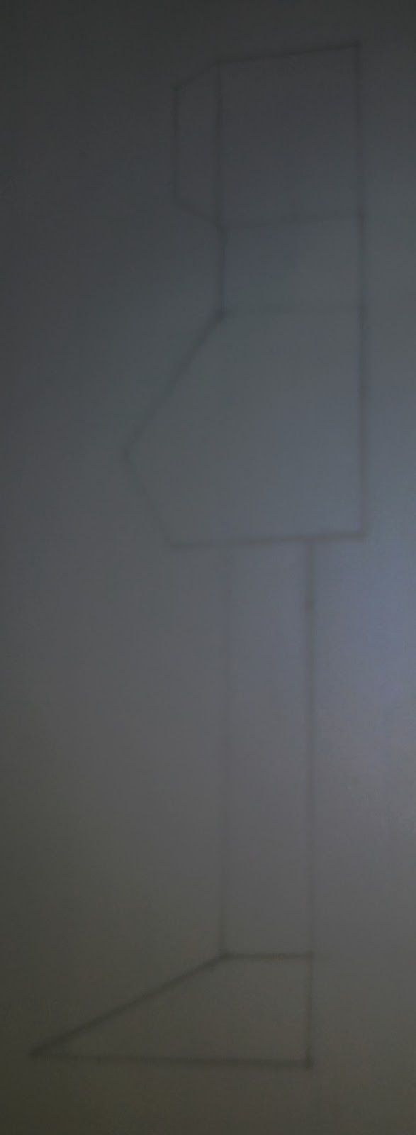
To follow this tutorial, you need to download Gundam blueprint. Open file gundam_fullbody_start.max. Save as this file. I will create arm in separate file, different from head and body. First, create a closed line like image below. Use Initial Type=Corner and Drag Type=Corner. When finished, apply Extrude Modifier with amount=8. After that, convert this object into Editable Poly.
In Perspective viewport, (1) Select both sides of polygons. (2) Apply Inset. (3) Move two selected polygons up a little bit. (4) Select polygon in one side only (front side) and in Left viewport move to the right. (5) Rotate view in Perspective viewport until you can see the back side. Select several polygons like image below. (6). Extrude. Make sure you extrude long enough. (7) Delete extruded polygons.
Turn off all sub-object selection. Apply transparent material. Then, apply Symmetry Modifier with Mirror Axis=Z. In Modifier Stack, click plus sign (+) right next to Symmetry. Highlight Mirror. In Left viewport, move mirror axis to the center of arm based on blueprint behind.
Right click shoulder object and convert into Editable Poly. Rotate view in Perspective viewport. (1) Select 4 polygons like image below. (2) Apply Bevel. (3) Use Inset. (4). Use Bevel again, this time inward.
Next step, you are going to create some detail, an U-pipe on top of shoulder
Creating Detail On Top of Shoulder
Next, Go to Create>Shapes tab. In Left viewport create a line like a letter "n". Tips: Hold Shift while creating line to make straight line. Then create small circle. Select letter "n" line, Go to Modify tab. Activate Vertex selection. Select 2 vertices on top of line. In Edit Geometry rollout increase Fillet value to 3. You'll have rounded corner. When finished, turn off all sub-object selection.
Go to Create>Geometry tab. Choose Compound Objects from drop down list. Make sure letter "n" line is selected. Click Loft button. In Creation Method rollout, click Get Shape button and click circle in viewport. You'll have pipe with letter "n" shape. In Skin Parameters rollout enter Shape Steps=1 and Path Steps=2 to reduce polygons in pipe object.
Finally, move pipe object into its position on shoulder object. You need to rotate in Front viewport also.
After you have created shoulder in previous tutorial, now you will create upper arm. In Gundam mecha, upper arm consist of 2 objects. One is hidden inside shoulder object, and the other is connected to some unique joint (also functions as an elbow) to lower arm.
Creating Upper Arm
In Front viewport, create 2 boxes. Use parameter like shown in image below. Position one box on top of another. Make sure they have small distance to each other.
Convert all boxes to Editable Poly. Select top box, activate Polygon selection, select top polygon. Apply Bevel a little bit. Then select bottom box. Select two polygons in the bottom part like image below. Apply Bevel.
In Left viewport, modify vertices position to match blueprint behind (left image). Change selection to Edge. Select all vertical edges in top box, and in Edit Edges rollout click Setting button right next to Chamfer. Enter Chamfer Amount=2. Repeat the process with bottom box. Make you chamfer just the outer corner edges (8 edges). Right image shows final result after chamfering.
Change to Vertex selection. In Front viewport select all vertices in bottom part. Use Select And Move tool along X axis to reduce width. Then in Front viewport, create cylinder like image below.
Convert cylinder to Editable Poly. Select one cap polygon (leftmost image). Apply Bevel. Then, use Inset..
Change to Edge selection. In Edit Geometry rollout, click Cut button. Turn on 3D Snap toggle. Next, cut twice like image below (from A to B). Note: Finish cut with right click.
Back to Polygon selection again. Select two polygons like image below. Apply Bevel inward. After that, turn off all sub-object selection. Make sure cylinder is selected. Click Mirror button (Tools>Mirror). Use Mirror Axis=X, Clone Selection=Copy. Adjust Offset value until you get proper location for the cloned cylinder.
It's time to create arm joint (elbow) and lower for your Gundam.
Creating Elbow and Lower Arm
In Left viewport create box, with parameters like image below.
Convert box into Editable Poly. (1) Modify vertices position. (2) Select all vertical edges and then apply Chamfer with Amount=2. (3) Select lower part polygons. (4). Apply slight Extrude to selected polygons. Then, use Select and Uniform Scale tool to make selected polygons bigger (just a little bit). Adjust selected polygons position when necessary. Rightmost image shows final result. This object will be used as an arm joint (elbow).
Next, we are going to create lower arm. In Front viewport create closed line like image below. I create the line a little bit to the left, not the same as blueprint, because I want all objects constructing the arm stay in straight vertical line axis. When finished, apply Extrude modifier with Amount=6.
Convert lower arm object into Editable Poly. Select all polygons. In Edit Geometry rollout, click Slike Plane button. Slice Plane is used to cut polygons along a plane. You just need to rotate this plane. After you managed to get plane position like image below, click Slice button.
Change selection to Edge. Select all vertical edges in front faces (one side only, there are 6 edges you need to select). Apply Chamfer with Amount=2. In Perspective viewport, rotate view until you can see the back side. Select one polygon like image below. Apply Extrude.
Turn off all sub-object selection. Apply symmetry with Z axis. Move Mirror axis to fit create best lower arm shape.
Final detail for lower arm. Select all polygons in bottom part of lower arm. Apply Inset and Bevel.
Creating Hand and Fingers
First, you will create the palm of the hand. Create a box in Left viewport. Use parameters like image below. Apply transparent material to this box.
Convert box into Editable Poly. (1) Select 3 polygons like image below. (2) Apply Extrude a little bit. (3) Activate Vertex selection. In Left viewport, move vertices in the middle closer to the edge. (4). In Front viewport, modify vertices position. (5) Select 2 polygons like image below. Apply Extrude. (6) Modify vertices in Front viewport. (7) Select vertical edges in front faces (4 polygons). (8) In Front viewport, move selected edges to make the box has no sharp corners.
Next, fingers. Create small box like image below. (1) Convert this box into Editable Poly. Select top polygon. (2) Apply Inset. (3). Use Extrude. (4) Select 2 edges. (5). Apply Chamfer.
Next, change to Vertex selection. Modify vertices position. When finished, turn off all sub-object selection. To create other fingers, just copy this box (hold Shift+drag) and arrange in order. Move vertices and scale if necessary.
Last finger: Thumb. Select one polygon on palm object. Extrude. Modify its vertices like image below. Just copy from other fingers and rotate to create thumb. Note: My mistake. I supposed to create left hand, but unfortunately what I created is right hand. So, I just mirror it later.
Final detail. Select polygons like image below. Apply Inset and Extrude. This extruded polygons will be used to connect hand with lower arm.
Final task, attach several object with another object.You just need to attach pipe with letter "n" shape into shoulder object. And 2 cylinders with upper arm object.
Sample of rendered Gundam hand.
Below is the model that I created.
LEG
Creating Upper Leg
To follow this tutorial, you need to download Gundam blueprint. Open file gundam_fullbody_start.max. Save as this file. I will create arm in separate file, different file from head, body, or arm. Creating upper leg is almost the same with creating arm. We start by creating.closed spline in Left viewport. Use Initial Type=Corner and Drag Type=Corner. After that, apply Extrude modifier with Amount=35.
In Perspective viewport, rotate view until you can see bottom view. Convert object into Editable Poly. Activate Polygon selection. And select all bottom polygons. Apply Inset and give slight Bevel inside.
Select top polygon. Use Inset and Extrude. Make sure you give long enough extrusion. Change selection to Edge. Select 2 edges in top area (look at image below). Apply Chamfer. Give this object transparent material. In Left viewport, modify vertices position if necessary.
Activate Edge selection. Select all vertical edges in four corners (look at image below). In Edit Edges rollout, click Settings button right next to Chamfer. In opened dialog box, fill Chamfer Amount=2 and click OK. Turn off all sub-object selection. Upper leg object is finished.
After you created upper leg in previous tutorial, now you are going to create lower leg for your Gundam. Lower leg modeling will be more difficult, especially in calf area. But, I will try to use simple modeling step.
Creating Lower Leg
In Top viewport, create ChamferBox. Use values like image below. Position this ChamferBox under upper leg. Apply transparent material. Hide upper leg object if you want.
Convert ChamferBox into Editable Poly. Activate Vertex selection. In Left viewport, use region selection to select vertices like image below. In Soft selection rollout, activate Use Soft Selection. Use Falloff=42.6 and Bubble=0.86. Don't deselect anything and apply Spherify modifier in Modifier Stack. You'll get nice shape for calf of Gundam leg.
Convert object into Editable Poly. Activate Vertex selection. Select all vertices in top area (look at image below). In Edit Geometry rollout, click Z button right next to Make Planar. Repeat the same procedure with vertices at the bottom area.
Modify several vertices position based on blueprint behind. Use image below for reference.
Next, you are going to add more details in knee area.
Adding Knee Details
Activate Edge selection. Activate 3D Snap Toggle. In Edit Geometry rollout, click Cut button. Then cut in front of object like image below. When finished turn off Cut and 3D Snap Toggle. Next, activate Vertex selection. Move vertices closer to the center in Front viewport. Tips: select both right and left vertices and drag Select And Uniform Scale tool along X axis.
Change to Polygon selection. Select polygons like image below. Apply Extrude. Activate Vertices selection and in Left viewport move vertices based on blueprint behind.
Another deteail. Select polygons in front faces. Apply Bevel. Move vertices in Left viewport if necessary.
In Perspective viewport, rotate view until you can see top area of object. Select polygons like image below (left image). Apply slight amount of Extrude. Reduce polygon selection (middle image below). Apply Extrude three times.
Change to Vertex selection. In Left and Front viewport, modify vertices position to match blueprint behind.
Next, you are going to continue creating lower leg.
Extending Lower Leg
In Perspective viewport rotate until you can see bottom part of object. Select all bottom polygons. Bevel 3 times. Watch Left viewport to match how much bevel amount is needed. In Left viewport modify vertices like right image below.
Select several bottom polygons in the middle. In Front viewport, move these selected polygons up a little bit. Then apply Extrude.
Activate Vertex selection. Modify vertices position like image below. When finished, turn off all sub-object selection. Try to render and watch weird faces render. The solution is to apply Smooth modifier to object with Auto Smooth active. After that, convert object into Editable Poly.
Create cylinder like image below. You can create this object using the same process like you did for the arm.
Another details, create one Chamfer Cylinder in Left viewport. Create 2 torus object also in Left viewport. Use values like image below. Position Chamfer Cylinder in the middle of two torus. Note: Chamfer Cylinder can be found in Extended Primitives drop down list, and Torus in Standard Primitives drop down list.
Image below shows finished upper and lower leg.
Now, it's time to create foot model. Creating this model is easier than it looks.
Creating Foot
Create 2 closed spline. Use Initial Type=Corner and Drag Type=Corner. Select one spline, go to Modify tab, in Geometry rollout click Attach button. Then click another spline in viewport to combine into one.
Apply Extrude. Use Amount=65. After that, in Command Panel go to Hierarchy tab. Click Affect Pivot Only button and click Center to Object. When finished, turn off Affect Pivot Only. Next, apply Taper modifier. Taper is used to make one side of object smaller than the other. Use Amount=-0.2, Primary Axis=Y and Effect Axis=Z. Because you moved Pivot to the center, taper effect will be distributed evenly in right and left side.
Convert object into Editable Poly. Select all polygons on top of object. Apply Bevel once. When you apply bevel, watch Front viewport to find out how much bevel amount is needed. Make sure foot object looks like a truncated pyramid in Front viewport.
Change to Vertex selection. Modify vertices position like image below.
Next, we are going to add details in the back of foot object. Change selection to Edge. Select all horizontal edges like below. Tips: just select one edge and click Ring button in Selection rollout. Click Settings button right next to Connect. In opened dialog box, enter Segments=2. Also modify Pinch and Slide value to make connecting edges created far away from center. Repeat the same process, to make another connecting edges in other side. After that create one segment of connecting edges at rear.
Select 3 polygons like image below. Apply Extrude twice. In Left viewport, modify vertices position based on blueprint behind.
Select 2 polygons like image below and apply Extrude.
By the time you finish this tutorial, you will have complete head, body, arms and legs. Enough to build your own 3D Gundam model.
Creating Foot Cover
Next, create closed spline in Left viewport (look at image below). Apply Extrude with Amount=4.
Convert object into Editable Poly. (1) Select 4 edges. (2) Use Connect to create connecting edges. (3) Modify vertices position if necessary. (4) In Perspective viewport, rotate view until you see inner side of object. Select one polygon. (5). Apply Extrude with adequate amount. When finished, turn off all sub-object selection.
Apply Symmetry modifier. Use Mirror axis=Z. In Modifier Stack, click plus sign (+) left of Symmetry. Highlight Mirror and in Top viewport move Mirror axis to create better object shape.
Let's add more details. Convert object into Editable Poly. Select two edges like image below. Apply Chamfer to eliminate sharp corners. Change selection to Vertex. Select vertices like right image below, and use Select and Uniform Scale tool to reduce object width.
Add detail using cylinder like you did in arm or leg modeling. Last step is to attach several object until you have 3 objects: upper leg, lower leg and foot.
Image below shows test render result.
As usual,below is my version of model.
Now, it's time to create shield for our Gundam RX-78-2 model. You will create this shield with easy steps.
SHIELD
To follow this tutorial, you need to downloa Gundam shield blueprint. Open file gundam_shield_start.max. This file contains plane mapped with blueprint image. Start by creating a plane in Left viewport. Use values below. Apply transparent material to this plane.
After that, convert plane into Editable Poly. Activate Polyon selection. Select and delete half of polyons. Next, go to Vertex selection. Modify vertices position to match blueprint behind.
(1) Select vertices like image below. (2) In Front viewport, move selected vertices to the left. Then, select only 2 middle vertices and move farther. (3) Change to Edge selection. Select 3 horizontal edges like image below. In Edit Edges rollout, click Settings button right next to Connect. In opened dialog box, enter Segments=2 and click OK.
Repeat creating connecting edges on other side. Also create top and bottom horizontal connecting edges (Segments=5).
Change to Vertex selection. Modify vertices position based on blueprint behind. Before you do, change Constraints in Edit Geometry rollout to Edge. This way, you won't change shield shape while modifying vertices position. When finished, change Constraints back to None and turn-off all sub object selection.
Apply Symmetry modifier.
Next step, adding details to the shield
Convert object into Editable Poly again. Select 4 polygons like image below. To select more than one polygons, hold Ctrl while clicking. Then, apply a little bit of Inset and delete selected polygons.
Turn off all sub-object selection. Apply Shell modifier with Outer Amount=3. Your shield model has thickness now.
Convert shield object into Editable Poly. Select polygons like image below. Apply slight Extrude to selected polygons. Next, you need to modify several polygons position. Select one side of previous extruded polygons (look at most right image below). In Left viewport, move selected polygons a little bit to the left. Repeat the same procedure to other side of polygons (but, move to the right).
Let's add some details in front and back of the shield. Select several polygons like image below. Apply Extrude.
Then, add details to the upper part of shield. Select 2 polygons at upper side of shield. In Edit Polygons rollout, click settings right next to Hinge From Edge. In opened dialog box, click Pick Hinge button Click one edge in viewport (shown in white arrow). You may need to zoom in to avoid picking the wrong edge. Use Angle=26. Look at result image below. Repeat the same procedure to other side of shield.
Change selection to Edge. Select two edges in previously hinged polygons. Move them backwards a little bit (along X axis). Next, change to Polygon selection. Select several polygons like image below and apply slight Extrude.
Next step adjusting the inner side of the shield
(1) Select edges like image below. Use Connect to create one segment connecting edges. (2) In Perspective viewport, rotate view until you can see back of the shield. Select polygons. (3) Apply Extrude. Then, in Edit Geometry rollout click Z right next to Make Planar. Move selected polygons forward or backward if necessarry. Most right image below shows the result.
In Left viewport, I create two cylinders in back of the shield. Look at image below for values and cylinder position.
Create a box in Left viewport. Use values like image below. Then convert into Editable Poly. In Left viewport, select most right vertices and drag them closer to each other along Y axis. Next, turn off all sub-object selection. You need to attach some object into one. Object inside red line is supposed to be one object. Objects outside red line is also needed to be attached as one object.
Final task. Do a test render and you will see soft edges. This is not what we want. Apply Smooth modifier, with Auto smooth=off. You will get sharp edges.
Below is the shield model that I've created.
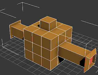
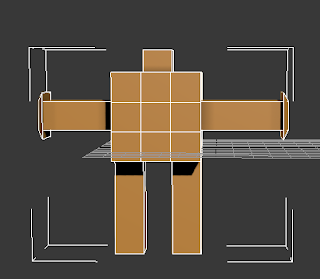
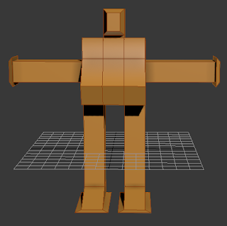
COMBINED PARTS
Below is the finish combined parts and consists of plain model.
Now we will begin texturing this plane model.
TEXTURING THE MODEL
After you finished all Gundam modeling tutorial, now it's time to texture the model. In this tutorial you will texture Gundam 3D model using Multi/Sub-Object Material. This material type lets you texture different polygon using different material. Basically you need to specify polygons to corresponding material ID.
1. In table below, I noticed that there's 7 colors needed to fully textured a Gundam RX-78-2 3D model. I also wrote specific ID to each color.
| ID | COLOR | Additional Information |
| 1 | WHITE | |
| 2 | GREY | |
| 3 | BLUE | |
| 4 | YELLOW | |
| 5 | RED | |
| 6 | DARK GREY | Only for Rifle |
| 7 | GREEN | Only for eyes |
We will focus on the head first. Base color for the head should be white (ID=1). Go to Modify tab and activate Polygon selection. Select all polygons and in Surface Properties rollout, enter Set ID=1. (Note: if you create Gundam object by yourself, you will have Editable Poly object and Material ID setting is located in Polygon Properties rollout).
2. Next, choose all polygons that needed to be textured using RED color. Set Material ID=5. Continue with other polygons and enter the corresponding ID (refer to table above). You can modified your colour to your liking.

3. When finished, you need to create material. Turn off all sub-object selection. Open Material Editor. By default, one sample slot is selected. I changed material name into "basic color". Apply this material to head object (you can click Assign Material to Selection while head object is selected). Click Standard button. In Material/Map Browser window, choose Multi/Sub-Object. In Multi/Sub-Object Basic Parameters rollout, click Set Number and enter 7. You need 7 sub-materials. Notice that each sub-material has its own ID. Then, click button under Sub-Material. You will go to each sub-material settings. Change sub-material name and change its diffuse color. Use color described in table above. When finished, click Go to Parent window to go back to Multi/Sub-Object Basic Parameters rollout. Repeat the process until each sub-material has its own name and color.
4. Finished textured head object.
This is my model of Gundam head.
5. Use the same process to apply material to all body parts. Set polygons to their specific IDs. You can refer to image below how to choose IDs. All of these process may takes a lot of time, so be patient.
There are several Gundam body parts that has text or "sticker" attached, like in left and right shoulder, and shield. You will create that "sticker" now.
1. First, hide all objects except right shoulder. Zoom in and capture the screen (Press PrintScreen button in keyboard). Open Photoshop, choose File>New and press Ctrl+V. Crop image like image below. And draw or add text (white text on top of black color). Also create a black color image.
You can right click this image and save to use later in later step. For example save as gundam_rshoulder_mask.jpg
Right click and save this image as black.jpg
2. Next, you need to create unique material for right shoulder object. Open Material Editor. Drag "basic color" material to another unused slot to make material copy. Apply this material to right shoulder object. Name this material "right shoulder". In Multi/Sub-Object Material, click Add button once. You will get new sub-material with ID=8. Click and drag from "white" sub-material to make copy of this material. Make sure you use clone method: Copy.
3. You need to modify this sub-material clone. Click this sub-material. Rename this sub-material. Click None button right next to Diffuse Color. In Material/Map Browser window choose Mask. In Mask parameters, click button right next to Map and choose Bitmap. Use any black image you have. Click Go to Parent button. This time click button right next to Mask. Choose Bitmap, use image you created earlier (gundam_rshoulder_mask.jpg).
4. Right now, you don't have any polygons with ID=8. Select right shoulder object. Activate Polygon selection. In Top viewport, select front polygons. Then set ID=8.
5. Do a test render, now you will have black text appear. Look at image below to understand how this works. Noticed that you have white base color. Then you have black image map and mask image. Map and Mask image work together. Mask image works like opacity channel. It control tranparency in map image. White color area in mask image lets the same location in map image appear when rendered. Otherwise, black color area in mask image make the same area in map image transparent.
6. Unfortunately, text location in right shoulder object is not right. Apply UVW Map modifier to right shoulder object. Use Planar Mapping type, then activate Flip in U Tile. Note: Mapping type and Flip is differ from one object to another. Other object sometimes doesn't need Flip active.
7. You can do the same process like above to any other part of Gundam. For example, I applied the same techniques to left shoulder and shield. For shield, because I want white text, I used white color image as map.
You can use this image below as Mask image in left shoulder object.
You can use this image below as Mask image in shield object.
Below is the finished video of my version of Prototype Gundam.
Thanks to Didik Wijaya for this wonderful sharing of tutorial and all the credits to him. This tutorial also is written for my own Gundam and there are differences between our Gundams.