The first step in modelling a Mech (that kinda looks like ED 209 from the Robocop movie) is the planning stage.
Repeat the same process with the side view of the blueprint. Now we can set the blueprint at 3Ds Max but first we need to set up our Project Folder and Unit Setup. After we have set up both, create a Plane that has similar size with the blueprint (you can check the size using photoshop - Image > Image Size).
Select the top polygon of the box and use Extrude (click on the small box beside the button to adjust the size of the extrude).
Select the polygon as shown below and extrude it once again. Adjust the vertices to match the blueprint.
Select the bottom polygon as shown on the picture and extrude the polygon. Adjust the vertices to match the side blueprint.
 |
| The polygon that need to be select and extrude. |
 |
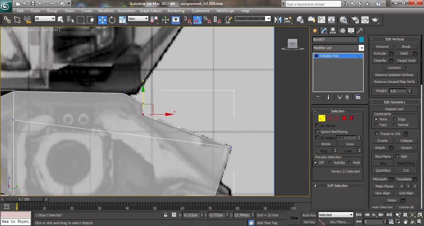
Adjust the vertices to match the side blueprint.
|
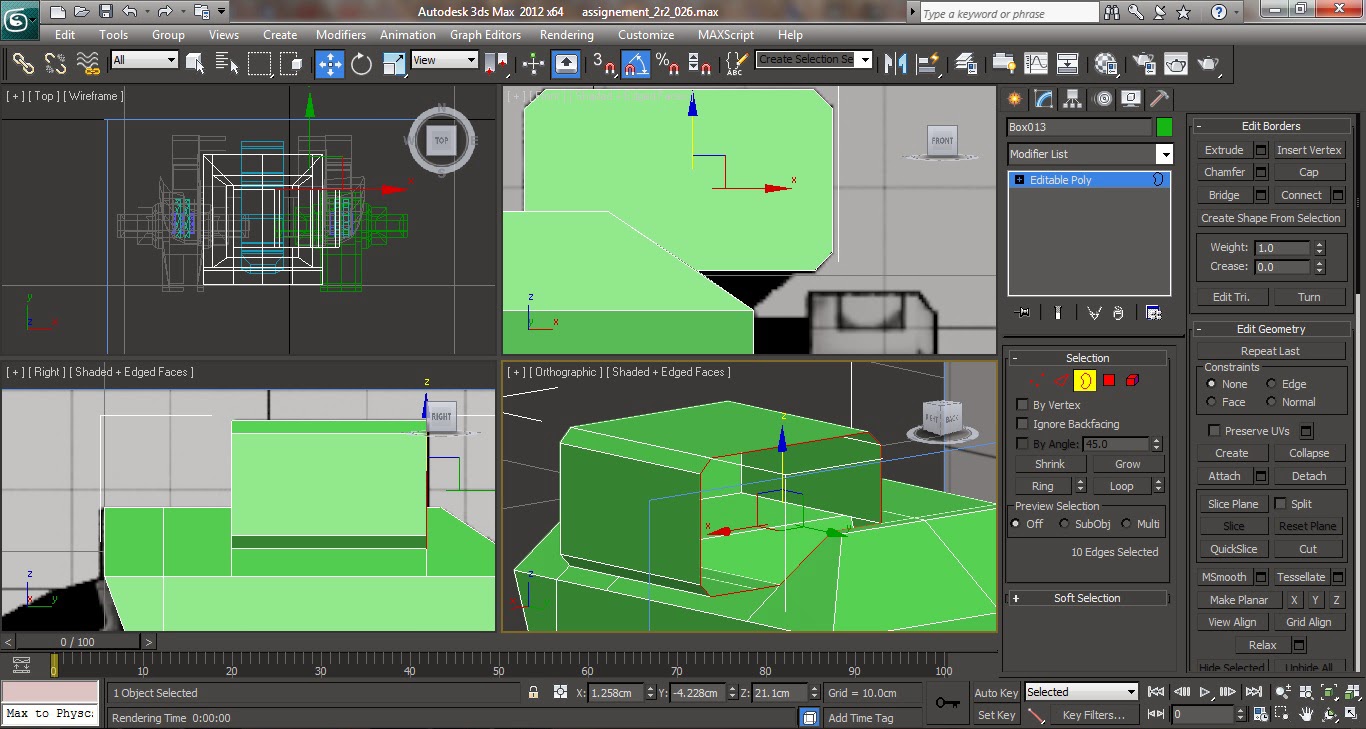
Now that the base of the feet is almost complete, select the edges as shown in the 3 pictures below (the red highlighted edges) and
Connect the edges.
 |
| Select these edges (hold Ctrl on the keyboard to hold multiple edges) |
 |
| Select these edges (hold Ctrl on the keyboard to hold multiple edges) |
 |
| Select these edges (hold Ctrl on the keyboard to hold multiple edges) |
 |
Connect all of the edges.
|
After connecting the edge another edge will appear in the middle of the feet. Using the polygon selection delete the left half part of the foot.
 |
Delete the highlighted half of the foot.
|
Now turn to the
Right Viewer in 3Ds Max and using the
Cut tool cut a shape roughly based on the polygon shape (the foot extension) in the middle of the feet blueprint. After that, select the polygon on the was cut and delete it.
 |
| Cut a shape base on the extension polygon on the foot's blueprint. |
 |
| Select the polygon and delete it. |
 |
The end result after deleting the polygon that was cut.
|
Now select the
edges of the polygon that was cut and while holding
Shift on the keyboard drag the mouse to copy the edges.
 |
| Select the edges as seen above. |
 |
Copy (hold Shift in the keyboard) the edges.
|
Adjust the edges to match the front blueprint. After adjusting it, select the edges of the copied one and copy it once again (using the same method as before) to extrude it. Adjust the vertices to match the right side of the blueprint.
 |
| The edges that were copied. |
 |
Adjust the vertices to match the blueprint.
|
Repeat the method of copying the edges from the new edges and adjust the vertices to match the blueprint.
 |
| Copy the edges from the new edges. |
 |
Adjust the vertices.
|
Select the edges at the top right and bottom right (base) of the new edges. Use the
Bridge tool from the
Edit Edges menu. A new polygon will now appear between the two edges and connecting it. Repeat the same process with the top left and bottom left edges.
 |
| Select the two edges. |
 |
| Using the Bridge tool. |
 |
| Select the two edges from the left side. |
 |
Again use the two bridge tool on these two edges.
|
Copy the new edges and adjust the vertices to match the blueprint.
 |
| Copy the new edges, |
 |
Edit the vertices to match the blueprint.
|
Now copy the
upperside of the new edges and adjust the edges to match the blueprint.
 |
| Copy the upper edges. |
 |
Adjust it to match the blueprint.
|
Now select the sides and bottom edges, copy the edges. Adjust the vertices to match the blueprint and to cover up the feet. Now select the bottom edge and the upper edge that is hanging out, use the
Bridge tool to cover up the feet fully. Adjust the vertices again to match the blueprint. Use the
Weld tool from the
Edit Vertices menu to close any gap on the vertices.
 |
| Select these edges. |
 |
| Copy the edges to match the blueprint. |
 |
| Adjust the vertices to match the blueprint and covering up the feet. |
 |
| Select the bottom edge and the upper edge that is hanging out. |
 |
| Cover up the gap using Bridge tool. |
 |
Adjust the vertices and use the Weld tool to close any gap on the vertices.
|
Now select the object (feet) and
Symmetry for the modifier list. Now the other half of the foot will appear. You can adjust the mirror (under the symmetry tab) if the other half is too far away.
 |
| Use the Symmetry modifier from the modifier menu list. |
 |
| Adjust the distance using Mirror under Symmetry tab. |
 |
The Final result of the Mecha's foot.
|
Next we are going to make the joint
for the Mech's foot. Create a small thin cylinder and position it to match the blueprint. Copy 2 more of the cylinder (hold Shift on the keyboard and drag the cylinder) and position it to match the front side of the blueprint.
 |
| Create a thin cylinder. |
 |
| Position the cylinder to match the side view blueprint. |
 |
| Position the cylinder to match the front side of the cylinder. |
 |
Copy 2 more cylinder and position it to match the blueprint.
|
Now copy 2 more of the cylinder and change the cylinders' side to 8. Adjust the size, rotation and position to match the blueprint.
 |
| The front view of the cylinders. |
 |
The side view of the cylinders.
|
Now hide the cylinders (using the Hide Selected that can be found by right clicking the objects) so we can have a better view to make the Mech's leg Create a
Plane with 4 segments, convert it to
Editable Poly and adjust the vertices to match the blueprints.
 |
| Create a plane with 4 segments. |
 |
| Adjust the vertices to match the front blueprint. |
 |
Adjust the vertices to match the side blueprint.
|
Now copy the edges of right side of the 4 segments (via hold Shift and Drag), adjust
it's vertices to match the blueprint. Repeat this step two more times so that the plane is covering the part of the leg in the blueprints. Make sure that the shape is somewhat rounded as the blueprint.
 |
| Copy the edges of the segments. |
 |
Repeat the steps two more times and adjust the vertices and edges to make it round shape.
|
Copy the
edges of the 4 segments but this time
for the left side. Adjust the vertices and edges to make match the blueprint. Next use the
'Bridge' to close the back of the part of the
mech. Select the top and bottom holes of the
part and close them. To do this, you need to click on the '
border' button from the modifier menu, select these 2 holes and press the '
Cap' button.
 |
| Copy the edges and adjust it as shown in the picture. |
 |
Use the bridge button to close the gap behind the part.
|
Now create a box shape with two segments
horizantally. Place the box inside the
part. Next select the polygon behind the box and extrude it.
 |
The placement of the box and the extruded polygon.
|
Now selecting the same polygon as above use
'bevel' to create a bevel polygon on the box. Now resize the bevel polygon to make it more narrow.
 |
| Bevel the polygon. |
 |
Resize the polygon to make it narrower.
|
Now extrude the top polygon of the box to match the side blueprint and adjust the vertices accordingly to match the blueprint. Extrude the top polygon two more times and adjust the vertices and edges accordingly to match the blueprint.
 |
| Exturde the top polygon. |
 |
Adjust the vertices to match the blueprint.
|
 |
Extrude two more times and adjust the vertices to model it like above.
|
To make the upper part of the leg, we will start by making a box like below.
 |
The position of the box.
|
Transform the box into an editable poly, then pick the selected edges and chamfer them as shown below.
 |
The chamfer edges.
|
Select the 2 polygons as shown below and extrude them.
 |
| Select these polygons. |
 |
| Extrude the polygons. |
 |
| The vertices needs to be adjusted to match the blueprint. |
 |
The adjusted vertices.
|
Now add a cube in the place that is shown below because as we can see on the blueprint. Extrude the side surface of the polygon and reduce the size of the polygon
.Use the chamfer tool around the cube to make it more mechanical look.
 |
| The placement of the cube. |
 |
| The polygon is resize. |
 |
Chamfer tool is use around the cube.
|
Using a box with 3 width segments. I created the part which is between the legs and the body. Adjust the vertices to match the front blueprint.
 |
| The placement of the box. |
 |
Adjust the vertices to match the blueprint.
|
Now we can start to model the body. We will start with a cube, adjust the vertices to match the blueprint.
 |
| A cube is created for the body. |
 |
Adjust the vertices to match the blueprint.
|
Extrude the polygon behind the
cube and use the
'Cut' tool for the edges to create an edge. Now adjust the vertices to match the blueprint.
 |
Extract the polygon.
|
 |
Adjust the vertices to match the blueprint.
|
Use the
'Cut' tool on the part as shown below. Then adjust the vertices to match the blueprint.
 |
| Use the cut tool as shown above. |
 |
Adjust the vertices as shown above.
|
Now select the edges on the front of the part as shown below and use the
'chamfer' tool.
 |
| Use the chamfer tool for the top and bottom edges. |
 |
Use the chamfer tool on the left and right edges.
|
Now copy the whole leg part to make the right leg.
 |
Copy the leg and adjust the mirror axis.
|
Now create a box with 2 width segments. Delete half of the
part and use
'symmetry' modifier on the box.
 |
Delete half part of the box and use symmetry modifier.
|
Adjust the vertices and extrude the top polygon 3 times and adjust the vertices as shown below to match the blueprint.
 |
Adjust the vertices to match the blueprint.
|
Now extrude the top polygon one more time and adjust the vertices to match the blueprint. Next extrude the two top front polygon as shown below and adjust the vertices to match the blueprint.
 |
| Extrude the top polygon. |
 |
| Extrude the front of the two top polygon. |
 |
| Adjust the vertices to match the blueprint. |
 |
The final outcome of the base body.
|
Convert the symmetry body to editable poly. Select the edges as shown below and connect the edges using the parameter given below. Adjust the vertices to match the upper cannon of the
mech as shown in the blueprint.
 |
| Select the edges as shown. |
 |
| Connect the edges using these parameters. |
 |
Adjust the vertices to match the blueprint.
|
Select the edges as shown below and connect them.
 |
| Select the edges. |
 |
| Connect them using these parameters. |
 |
| Select these edges. |
 |
Connect them using these parameters.
|
Select the polygon that was made with the connected edges and delete the polygon. Now select the right edge of the hole and copy the edge three times as shown below to match the blueprint accordingly.
 |
| Delete the polygon as shown. |
 |
| Select the edges. |
 |
Copy it three times and adjust the edges to match the blueprint.
|
Again copy the edges as shown in the picture below to cover the top and side of the cannon.
Next select the edges shown below and use
'target weld' to weld the cannon to the body.
.
 |
| Target weld the edges shown in the picture. |
Now close those 2 holes in the front and back of the cannon by clicking on the '
Border' button from the modifier menu and then click on the '
Cap' button.
 |
| Select the border. |
 |
| Use Cap on the border. |
 |
| Select the back border also. |
 |
| And use the Cap button. |
Select the front polygon, then use the inset tool as shown in the picture below. Adjust the vertices to match the blueprint. Next extrude the polygon.
 |
| Use the Inset tool on the polygon. |
 |
| Adjust the vertices to match the blueprint. |
 |
| Extrude the polygon to make the polygon appears inside the cannon. |
Create a small cylinder for the cockpit. Delete the back of the polygon and select the edges around it. Adjust the vertices and edges using the rotation tool and scale tool to match the blueprint of the cockpit covering it in the process.
 |
| Create a small cylinder. |
 |
| Delete the back of the polygon. |
 |
| Adjust the vertices to match the blueprint. |
 |
| Adjust the edges to match the blueprint. |
Copy the edges selected as shown above and below three times while adjusting the edges and vertices accordingly.
 |
| Using the scale tool on the edges to adjust the edges. |
 |
| Copy the edges. |
 |
Adjust the edges to cover the cockpit area of the blueprint.
|
 |
| The final shape of the cockpit. |
Next create a small cylinder with 2 height segments. Resize the front polygon using the
scale tool and adjust the vertices accordingly as shown in the pictures below. Position the cylinder as shown in the picture below to match the blueprint.
 |
| Create a small cylinder with 2 height segments. |
 |
| Resize the front polygon. |
 |
| Adjust the vertices and position to match the blueprint. |
Select the back polygon of the body and extrude it. Use the
'Inset' tool on the polygon.
 |
| Extrude the back polygon of the body. |
 |
The parameter for the Inset tool.
|
Now for the arms, create a small box and adjust the vertices to match the blueprint.
 |
| Create a small box. |
 |
Adjust the vertices.
|
Extrude the polygon four times while adjusting the edges and vertices accordingly to match the blueprint.
Now use Inset tool for
mech shoulder and extrude it as shown below.
 |
| The parameter for the Inset tool. |
 |
Extrude the polygon that has been Inset.
|
Now create a small box for the
mech's hand. Extrude the side of the box. Select the top and bottom edges as shown in the picture below and use the
'Chamfer' tool. Adjust the vertices to match the blueprint.
 |
| Create a small box. |
 |
| Extrude the polygon. |
 |
| Select these edges. |
 |
The parameters for the Chamfer tool.
|
Select the front side of the polygon and use the Inset tool. Next adjust the vertices to match the blueprint. Then extrude the polygon so that it appears inside the cannon.
 |
| Select the polygon. |
 |
| The parameters for the Inset tool. |
 |
Adjust the vertices.
|
 |
Extrude the polygon.
|
Next select the back polygon of the hand and use the Inset tool. Extrude the polygon and adjust the vertices to match the blueprint.
 |
| Select the polygon. |
 |
| The parameters for the Inset tool. |
 |
| Extrude the polygon. |
 |
Adjust the vertices to match the blueprint.
|
Next extrude the polygon as shown below and resize it using the scale tool so that it appears like the second picture below.
 |
| Extrude the polygon. |
 |
| Resize the polygon using the scale tool as shown in the picture. |
Lastly on the modelling part, create a cylinder with 1 segments and 10 sides. Resize and place it to match the below picture based on the blueprint. And now we have the connector for the mech's arm and body.
 |
| The cylinder that will connect the body and arm of the mech. |
Here is the final model for the mech without material or texture.
 |
| The final model. |
SETTING UP TEXTURE AND MATERIAL
For the texture and material, I download from the internet some texture which I feel looks great on the mech. I then copy the picture file that I download from the internet to my project folder under
sceneassets > images. To insert the material use the
Material Editor on the top tab menu under
Render > Material Editor (use the compact editor for beginners) or simply just by pressing
'M' on the keyboard, the material editor will show up.
 |
The downloaded texture should go in this folder under
project folder (in my case my project folder is name Modelling)
|
 |
The menu to open the Material Editor or you could simply press 'M'.
|
 |
The Compact Material Editor.
|
To apply the material into the model first select the part you want to texture. Click the grey globe or the
'default mateial', you can determine the
type of shader you want to use under
Shader Basic Parameters, the default is
Blinn which people have told me is shader that looks like plastic but in our case we should use
Metal, but it depends what type of robot or mech you're trying to model. After I have adjust the parameter, I click on the small grey box beside the diffuse colour box and a Material/Map browser will appear. I double click on Bitmap under the standard stack and find my texture map picture that I can browse from my computer, in my case I use a TARGA format picture that I have crop and edit from Photoshop. I open my texture map and click on the third button mark Assign Material to Selection below the sample type and then I click on the fourth last button mark Show Shaded Material in Viewport. The material will appear in the part you selected.
 |
| The Shader type that you can use. |
 |
| The Diffuse button. |
 |
The bitmap 'Map' type.
|
 |
| Select the map you want from your computer. |
 |
| Assign materal selection button. |
 |
Show shaded material in viewport button.
|
But what if you want to select only one part of the model that is part of a whole part. Well that's easy simply select the part to editable poly and select the part using polygon selection. And repeat the same process as you did from the previous step. If you want to map the next part of the same whole part just simply convert the whole part to editable poly so the previous map will remain and you can go on to map the side arm for instance.
 |
| Select the polygon. |
 |
| Add the material using the previous step. |
 |
| Convert the part to editable poly so that you can edit the map on other part of the arm. |
 |
The part is ready to map.
|
In some cases the map will not match with what you had in mind. This is where
'UVW Map' modifier comes handy. After you have map using the previous steps, elect the
'UVW Map' modifier from the modifier list. Select the type of mapping you want in
UVW Map parameter that is suitable to the map you want to use, in my case I use
box. Now you can adjust your map by simly clicking the
'+' button next to
UVW Map modifier list,
'Gizmo' will appear under it select the
Gizmo and adjust your map to your heart content (you can rotate, scale and position it). Once you have finish adjusting the map to your liking don't forget to convert editable poly so you can map other part of the mech.
 |
| Sometimes when you map something like this will happen. |
 |
| UVW Map modifier comes in handy. |
 |
| The UVW map Gizmo comes in handy to adjust the map. |
 |
| The Final Map using UVW map (I use box and adjust the gizmo) |
Repeat the same process with other part of the mech, you can map and texture your map to your liking. This is my final Model of the Mech that has been texturized using UVW Map.
 |
| My Final Model and Texture. |
RENDER
Now that you have finish your model and have also map and texturized the model, it's time to render. You can render your using
'Render Setup' (it can be found on the top menu button). Now you the
'Time Output' you want to use,
Single means single frame in which it is suitable for picture while
Active Time Segment is the whole Frame that is use in the timeline (usually for animation or camera rotation) and lastly
Range is use for the specific frame length you want to use. Next select the
Files button under
Render Output, here is where you can specify where to save your file and the type of file format you want to use. Lastly when you finish setting your
Render Setup, the big button in bottom mark
Render is the render button that will render your model or animation.
 |
| The Render Setup button. |
 |
| The Time Output setting. |
 |
| The files button to save your files. |
 |
| The list of file format you can save. |
 |
| The Render button. |
 |
| The Final render file preview. |
So that's all the steps I use to model and texture my Mech, and also a bit on how to render.the model. Hopefully this tutorial is helpful to you.