Creating
projects and image references.
by, ANG JIEH SHIR D20111047306
To model a character in 3ds Max, first, we
need to have a model reference.
Basically, we need a front view, side view
and a back view.
Here’s an example of my own robot.
Now, open your 3ds Max software.
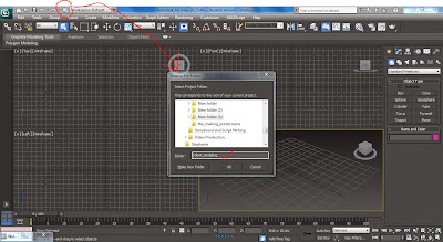
First and foremost, create a project before
you do anything.
Name your project folder with only SMALL
LETTERS and NO SPACING. If you want to separate the words, just use “_”.
For example : robotmodeling001 OR
robot_modeling_001
You have your project folder now, remember to
save your image references in the folder images.
robot_modeling > sceneassets > images
Now go back to your 3ds Max, set the unit
correctly.
Customize > units setup > system unit
setup.
Set your unit and click OK.
And now, create a plane.
Create panel > geometry > standard
primitives
There’s many types of objects can be choose
there but we need to insert our image references, so a plane will be a better
choice.
For front and back view, we make it
back-to-back.
For the side view, just rotate 90 degree via
z-axis.
From the top view, you can see it is like a
“+”
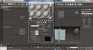
To insert the images to the plane, click on
the object which is the plane in this project. Then, press “M” on your
keyboard, it’s a shortcut key to the material editor.
Next, there’s a small square beside “diffuse”,
click it.
Another panel appear, click “bitmap”
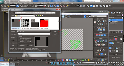
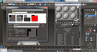
A window of images folder appear, choose your
image references you saved in the folder images just now, just double-click
your image reference. So here, we pick the back view for the robot.
And the image will map on the sphere in the
material editor.
Then, make sure the plane is selected, click
the mapped sphere in the material editor, click “show shaded material in
viewport” and click again “assign material to selection”. Then the plane is mapped with the back view of our robot. As shown in the print screen below.
Do the same steps to the front and side view
for your robot references. When you have your references done, as shown below,
you can now start your modeling.
Modeling
Refer to this reference, we start from the
head first.
The head looks more like a sphere. So, we
start from a sphere first.
Pick the sphere from the primitive panel.
Click and drag it at the perspective viewport.
Move the sphere to the right position in your
reference.
Next, we are going to edit the sphere so that
it matches our reference. Just select the sphere, right click on it, and choose
“convert to” > “editable poly”.
Open the “modifier list” > “editable poly” > “polygon”.
Then select half of the sphere and “delete”
it.
Now, you have only half of the sphere. Select
the “hemisphere” you have, go to the modifier list and choose “symmetry” and
click “show end result”. Now you will have the other side which is symmetry to
the other.
This is because we are modeling a mechanical
robot, the left and right side have to be similar.
With this symmetry tool, we model only one
side, and the other side follows.
Go back to modifier list, choose “FFD 4x4”
> “control points”.
At the viewport, you can see the control
points shaped like a box. Just move the points around to modify the sphere.
The sphere is opaque, you can’t see the
reference overlapped by the sphere, just press “alt + x” on your keyboard. You
will get an X-ray view, the selected object will become translucent.
Just continue modify the sphere using the
control points until it form the shape you desire.
For the upper body, choose “extended
primitive” > “capsule”, and modify it using the steps mentioned above.
Same goes to lower body, “extended primitive”
> “tube”, and modify it using the same steps.
For the arm, “cylinder” and “sphere” are
used.
A slight adjustment are made using editable
poly.
After one arm is done, select the whole arm,
right click it, > “clone”.
Click and drag out the cloned arm, give it a
180 degree rotation will do, and drag them to the right position.
The eye part, “sphere” is use, just convert
it to editable poly and modify it as “FFD 4x4”, and drag the control points to
model it.
And then just drag it to the head and locate
it at the eye part.
Texturing
There’s a few ways in doing texturing on your
model. Here, for this robot, I used 2 type of texturing, which is using the
material editor and unwrap UVW.
Material editor mapping:
I apply this mapping on the arms, lower body,
hair, and ribbon.
Select objects you desire to texture, press
“M” on your keyboard, the material editor panel appear. Click on the default
sphere in the material editor > diffuse > then select any colour you like
> assign it to your object. The steps are same as doing the image reference
at the first place.
Unwrap UVW :
I apply this mapping on the robot eyes and
body.
At the modifier list > “unwrap UVW” >
“face” > “open UV editor” > “mapping” > “unfold”.
When you see the unfolded object, select the faces you want to separate, break it.
At the selection panel > pick texture >
choose the texture saved in the images folder.
Here, I already prepare the colour texture I
needed for the eyes part, which is only grey and black.
move the break part to the black colour part. Left the
rest at the grey part.
Then open the material editor, at “map” >
“bitmap” > choose the colour texture just now > assign it to the object.
Now, you see the eye part of my robot is map
with 2 different colour.
A model of a robot is now done.


No comments:
Post a Comment
Note: only a member of this blog may post a comment.