Sunday, 10 November 2013

“Modeling a Robot tutorial”

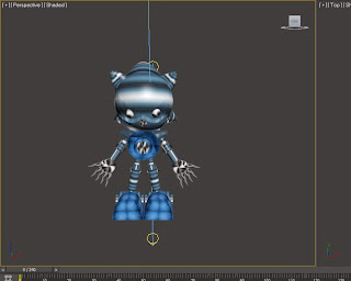
Robot Tutorial by Nabilah Sihar


          “Modeling a Robot tutorial”

         Nabilah Binti Sihar
        D20111047330


Modeling a Mechanical Model
Planning stage :
-Modeling a Head
-Modeling a Body
-Modeling Legs
-Texturing

 Image References


The Process
1.   Modeling a Head


 a.    Create a Sphere from Standard Primitive selection. This will be the model basic shape
       for its head. 
 b.   To do its eyes that has that kid of shape. right click on the selected object and then                click on the Convert to: convert to editable poly.              

 c.  To gives that shape click on the Cut and then follow the shape. After finish that, click             on the Polygon select all the shape of the eyes and then Click on the Extrude and then             move the tool to the back.

ears
eyes


front


head all finish


 d.   Then we add an eyes to the model by using sphere.
 e.    Next, the eyes will be duplicate/clone by right clicking on the object or by simply                   use CTRL+C  and paste CTRL+V.
 f.    The other parts of its head such as nose and ears head part are also using standard
      primitive object such as cone and cylinder.
 g.  The ears use the Convert to: convert to editable poly. and then make the shape like the        ears.Same goes with the thing on the top of the head. The others parts of ears use                    the CTRL+C  and paste CTRL+V. 


2. Modeling a body


a. This part of body use basic shape of the cone. and then Click on the Convert to editable poly to change the shape.


b. This part of the hand.The shape at the top use the cone shape and then click on the               Convert to editable poly to change the shape. 
c. And then to make the part of the hand we use the Cone in the Standard Primitive                  selection. 
d. To make the palm hand used the sphere and then click on the Convert to editable poly to      change the shape. For the fingers use the cone in the Standard Primitive selection. And the at the Upper circle click on the inset and the extrude to make the fingers long. CTRL+C  and    paste CTRL+V. 
e. To make another hands click Mirror.. 

3. Modeling a legs


a. At the above, the legs used the basic shape. Such as Cone. 


b. At the bottom take the basic shape and then click on the Convert to editable poly to change the shape.

c. To make another legs. Click on the mirror.


4. Texturing.

 a.    Open Modifier (M).
 b.    Select Basic Shader Parameter, turn it to Metal, then at Metal Parameter
        select Diffuse, pick a Bitmap.
c      And adjust the Spectacular Highlights and change the number of  the Level,and Glossiness.


Saturday, 9 November 2013

Mechanical Model Tutorial by Mohd Nazri


          “Modeling a Mechanical model tutorial”

                             Mohd Nazri Bin Idris

                                D20111047289


Modeling a Mechanical Model

Planning stage :

-Modeling a Head
-Modeling a Body
-Modeling Legs
-Accessories (bag)
-Texturing

 Image References


                                                                       Front                        Side


The Process

1.   Modeling a Head


 a.      Create a Sphere from Standard Primitive selection. This will be the model basic shape
              for its head. 
 b.     Extrude the sphere and make it a bit long.


                                   The shape can be edit by controlling the gizmo.


 c. Then we add an eyes to the model by using sphere, and to make it look like the model,
           the eye need to be modify by using Boolean. This can be found at compound object. 
           beside eyes, the nose are also using the same method.


       d.     Next, the eyes will be duplicate/clone by right clicking on the object or by simply use
             CTRL+C  and paste CTRL+V.
 e.    The other parts of its head such as mouth and back head part are also using standard
             primitive object such as Box and Sphere.


2. Modeling a body


a.       The bodies components are create by using standard object such as Box and Cylinder.


b.       Here is the component used, multiple object has been combine to create each part.


                      left side of the model has been dismissed to view the component used


   c.   Some of the part is created by modifying object. For an example the” waist part”.


     d.   Basic object used is a box and a cylinder (bottom).
.
     e   .Firstly convert the part into Editable Poly(right click).
          To see it clearly, change the view to wire frame mode.

     f.     At the section menu, click on vertex. From there the part can be modifying by
                controlling the gizmo.


            3.     Modeling Legs


         a.     Legs part are created by using Box and Sphere( joint). 


         b.  Some of the part were edit by using Editable Poly.


   4.   Accessories (bag)


                                      The bag is attached at the back of the model

     a. Basic object used is Box and Cylinder.


 4.   Texturing


                                                               The model without texture


    a.    Open Modifier (M).
    b.    Select Basic Shader Parameter, turn it to Metal, then at Metal Parameter
           select Diffuse, pick a color.


c       To make it more realistic, adjust the Spectacular Highlights and change
  the number of  the Level,and Glossiness.


   d.    Drag the color chosen into a model part.


                                                                              Final Render


Thursday, 31 October 2013

Modeling a desk fan

Planning stage:

  1. This fan is constructed 4 separated objects:
-         Fan Base/Stand
-         Motor
-         Vanes
-         Vane Cover

  1. These items can be constructed separated in a scene. Fan base should be built 1st, follow by the Motor, then the Vanes and ended by the Vane Cover.

  1. Identical progress of the model construction needs to be captured for elaborating purpose.

  1. Sketches of front and side view of a fan need to be placed in the viewing panel in order to create a more accurate model.

Front view sketch
Side view sketch

The Construction of Fan


Front view


Side view

 1.       Sketches of fan, both front and side views were brought into viewing panels by creating image planes.

2.       The sketches were darkening by lowering the Color Gain setting for minimizing the contrast between the viewing panels and the sketches.

Fan Stand in Perspective View


Fan Stand in Side View


  1. The fan stand was constructed by extruding a Polycube. The whole fan stand is basically in one piece.

  1. The Motor part of the fan was created by compiling 3 objects, which are 2 cylinders and a cube. All 3 object were combined together once the form

Creating Fan Motor


 5.      A Hemisphere was reformed to be the back cover of the fan motor. All the vertices of both cylinder and hemisphere were merged.

Completed Fan Motor

6.      2 cylinders were created for being the axle and the socket of vane cover.

Fan Axle and Vane Cover Socket were done.


Fan Vane creation and placement

 7.      By altering the vertices and scaling the size of a sphere, a fan vane was created. The fan motor was hidden temporary.

Edited Duplicate Options Window

 8.      The vane was then duplicated into 2 more copies with above setting.

Duplicated Fan Vanes


Creating the vane cover

9.       A sphere was created to form the Vane Cover of the fan. 3 layers were created for the fan, to locate the parts of the fan. Then all of the parts except the vane cover were set as template.

Deforming a sphere to create the vane cover


3 Layers were created
 10. The faces on the sphere were selected and extruded. Then the extruded surfaces were deleted to form the wired-frame like vanes cover.

Selecting sphere faces for extruding


11. Both sides of the sphere faces were extruded and deleted until the final look was formed.


Completed Vanes Cover


  1. A cube was created and rescaled to form the button of the fan. Then it was duplicated into 3 more copies.

Fan Speed Controlling Buttons


  1. Next, 3 materials were created for the completed fan model.

  1. Then a directional light together with an ambient light were created.

  1. Once the Lighting setting was, the final output of a render image was created.


Materials on Fan


Rendered Fan Model

© Tan Wee Hoe 2001. All rights reserved.