Wednesday, 1 January 2014

Tutorial Robot


By Nor Aishah Tajudin
    D20111047295


Tutorial Robot 


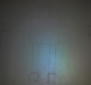
Image reference
The part of robot is:
  • Head
  • Body
  • Hand
  • Leg

    Head


To make a head robot:
  • Go to Command Panel, then standard primitives and take a sphere
  • Make sure the position of sphere is center
  • Convert the sphere to edit poly
  • Divide the sphere to 2 parts; left and right
  • Select either part to delete(in the picture)
  • Then adjust the vertex like the head of robot
  • The robot face:

  • The robot face also from sphere
  • To edit this sphere, it use the same technique as a head robot
  • Go to Edit poly > vertex, then select the vertex and adjust the shape
  • This face no need to divide to 2 parts
  • This part like a ear's robot:


  • To create this part, using the cylinder, then adjust the size.
  • Then, to complete another one ear, go to Modifier List > Symmetry, click the symbol (+) mirror, then mark the Flip, move the object(ear) to opposite direction
  • Or we can copy the ear and mirror that ear
  • This is neck of robot:


  • Using the cylinder shape and re-size.

Body


  • To create this body, using the plane
  • Add the plane based the size and shape of robot body


Hand And Finger


  • To create the hand, I using the same way like to create the body
  • Using the plane and adjust the vertex based on shape and size of hand.
  • Then symmetry that hand


  •  Create the finger using sphere and plane
  •  For sphere, scale until look long like a finger
  •  Then, when perfect create all finger, select all finger and group  them together
  •  The last one is symmetry the finger as all body part have a pairs

Leg


  •  Tutorial for leg of robot, I using plane also, and adjust the  vertex based on size and shape of leg's robot.


 The Finale Robot
Moies Robot

Monday, 30 December 2013

Robot combo

SITI FATIMAH BINTI HARUN
D20111047296


Modeling a Mechanical Model

                  1-Planning stage
                                          Mechanical  5 part :
·         Modeling  body
·         Modeling a head
·         Modeling a hand
·         Modeling the leg
·         Texturing

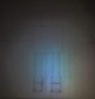
2.      Image References


Front

Back

Side


  •       Modeling body


Part of body created using by line,cylinder and box.
      a) Use the 'convert  to ' and choose the 'Editable Poly' to make their proper shape.
      b) In the body part tool   'Extrude ' using to make each side of shape become suitable.
      c)Adjust the amount and the segment at the parameter to get the perfect body shape.
      
Part of the body front
Part of the body back

     d) The part of  body robot, were created separately and then were combined together once all is done.

Part of the body front

Part of the body back


  •       Modeling a head
    a) Use the line and sphere.
    b) Use tool 'extrude' on the head to make it become  suitable.

Part of head

  •     Modeling a hand
part of hand
     a)Use the line, box and sphere.
     b)Extrude and choose the 'Editable Poly' to make their proper shape.
     c) The part of  hand robot, were created separately and then were combined together once all is done.


part of hand after joint


  •     Modeling  the leg.
Part of the leg front

Part of the leg back


    a) Use the line, box and cylinder. that must suitable for use to make a robot leg.
    b) Then go to convert after choose 'editable poly'. using this editable poly and then changes the shape through edge and vertex selection .it will make us easy to shape the robot leg.
    c) After finish combine, clone and make the other part of leg. The complete leg.

part of leg after joint

  • Texturing.
a) Lastly mapping the robot.
b)First, select button M or material editor.


c) Then, select part that we want to mapping.
d)After that click assign material to selection.


     e) Finally, setting the lighting  and render the robot.


Sunday, 29 December 2013

SUTHA D/O BALASINGAM

ROBOT TUTORIAL

MODELING (MMG3083)

SUTHA BALASINGAM
D20111047303


Modeling tutorial..

There are three stages in  the modeling a robot that is modeling a head, body and leg.

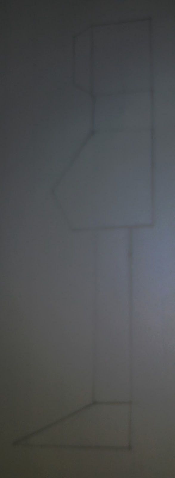
First we need to do an image reference with three side views that is front, back and side view.

                                 Front


               Side


                  Back


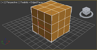
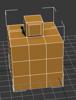
Secondly, create a box which is in the standard primitive selection to do the body of the robot and adjust the box parameters and set segments to 3. After that, convert the box to edged faces.


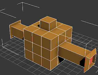
Thirdly, convert the box to the editable poly by right click on the box then select polygon and tick on the ignore backfacing box. Then choose the polygon on the centre of top box then right click choose to extrude the head  of the robot into small box to do the head of the robot. After that, choose bevel  to modify the head of the robot.

After beveling the head


Fourthly, do the same method to the both side of the box by extrude for create hand. To extrude the same size of the hand press ctrl button. After that use bevel tools to modify the edge of the robot hand.


After bevel at edge of the hand


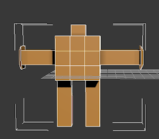
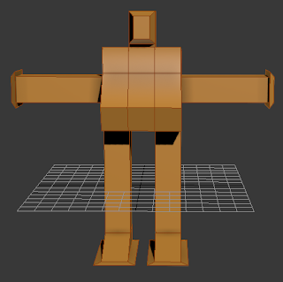
Fifthly, do the same method for the leg of the robot and turn the box downwards then select the polygon and ctrl and choose extrude to make the leg.


 Final robot after render


Saturday, 28 December 2013

Blood ASP Robot Tutorial

SITI NORSAKINAH BINTI AB.GHAFFAR
D20111047294


I want share how to model Blood ASP robot in 3Ds Max.
1. Image reference (blueprint)
2. Modeling a body
3. Texturing


1. Image reference (blueprint).
  • First of all, I search the blueprint image robot on internet. The name of robot that I choose is Blood Asp.
  • And then, I separate the views robot Blood Asp from the blueprint by using Adobe Photoshop.
  • Open the image in Photoshop and by using 'Rectangular Marquee Tool', select the front view from the blueprint and press 'Ctrl + C' in the keyboard to copy the selection that I've made.
  • Now, open a new document by press 'Ctrl + N' in the keyboard or do it by going to 'File > New' menu. When the New dialog box pops up enter the value of 240 pixels for width and 720 pixels for height, then click 'OK'. It all depends upon the size of the blueprint, as we may have to change the dimension for other blueprints. Make sure that it fits almost perfectly in the new document.
  • Now just press 'Ctrl + V' to paste the front view into the new document and save it as an image file in hard disk.
  • Do the same step for side view.


Front view

Side view


2. Modeling a body.
  • After set up a blueprint, we must to build plane to enter the front view and side view.

Build a plane

Blueprint set up


  • And then, click 'Shapes > Line' and trace that blueprint from front view and side view by using 'Line' tool.
  • Start with trace part the leg from the body of robot.
  • And then, click 'Modifier > Extrude' and adjust the number what amount that I want.


  • Do the same step for the other part of body robot.
  • But just doing for half of body the robot.
  • For see through, we can press 'Alt + X'.


Alt+X


  • After finished make / do trace by using Line tool for the half body of the robot, check the amount that I use for all the part that I do.


3. Texturing.
  • For the texture, open modifier by press M.
  • And then I choose image for texture the model of robot.
  • I choose 'Blinn' for my texture.
  • After that, drag that texture into robot.
  • Use the same step for other part of body the robot.
  • To get more interesting, adjust spectacular highlights and then  adjust the number of glossiness and specular level.
  • After that, click 'Mirror' for the half body of robot.


Finally, render the robot.